
Project Overview:
Project Description: We were given the task to design a digital circuit that displays the count from 00 to 80 with two control inputs and two control outputs. The two inputs are next and reset, with the next signal coming from a push button switch that, when pressed, advances the display by one. the reset signal, which is also a push button switch,will reset the display to a count of 00. When the display reaches 80 the count is supposed to cease. The employee at the deli counter takes a break and a new employee takes over the counter after the 80th customer is served.)
Multisim Circuit:
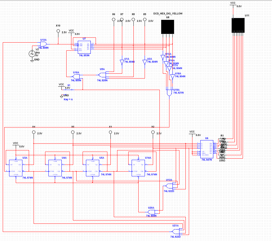
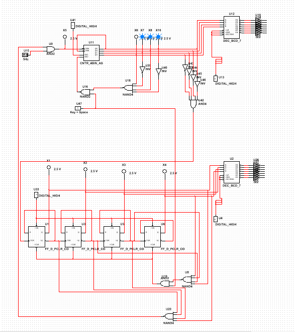
PLD Circuit:
Differences Between PLD and Design Mode:
Design mode in Multisim is faster than PLD mode when it comes to designing the circuit on the computer itself. This is due to PLD mode having the 9for the most part) exact same circuit as the design mode but with input and output connectors called pin assignments. Pin assignments are used to assign pins on the logic board to what will be wires once breadboarded. As soon as the breadboarding process begins, the ease of use shifts to the PLD mode. In PLD mode with the breadboard, there are far fewer wires that need to be stuck into the breadboard thanks to the logic board. Breadboarding in the design mode has many more wires because every input and output of the logic gates needs to be wired.
Bill of Materials:
If I had breadboarded this project, the materials I would need would be:
breadboard
spools of wire in different colors
wire strippers
(1) 74LS00
(2) 74LS04N
(1) 74LS08
(1) 74LS20
(1) 74LS21
(1) 74LS22
(1) 74LS47
(4) 74LS74
(1)74LS93
breadboard
spools of wire in different colors
wire strippers
(1) 74LS00
(2) 74LS04N
(1) 74LS08
(1) 74LS20
(1) 74LS21
(1) 74LS22
(1) 74LS47
(4) 74LS74
(1)74LS93
Final Project Conclusions:
All of my classmates had a different design than me. I decided to have a separate flip flop on the same clock as the 93 that counted up 1 every 10 rising edges.1. 1.Difference between SSI and MSI circuits: Small scale integration (SSI) circuits work with minimal input values and only one output value. Medium Scale Integration (MSI) circuits have multiple inputs, outputs, and other functions that can be applied if needed.
2. Limitations of my MSI circuit: MSI circuits only count in binary, the wiring of the circuit needs to be exact as the slightest mistake will produce something other than what you intended, require logic.
3. Meaning of “ripple effect": The "ripple effect" is technically called, propagation delay. propagation delay can be seen in asynchronous counters when the clock value changes and a brief flash of a number will show up during the transition between the number you want and the next number in line.
4. Set-up of my design: In the Jeremy circuit, once started, the clock and begins to count up in the ones place on every rising edge until it reaches 9. 9 triggers it to restart at 0. Every 10th rising edge, the tens column flip flop outputs a 1 and the display counts up one. Once the tens digit reaches 8 (making the entire number 80) the ones column stops at 0 and the clock stops. If I press the reset button after this, the display goes to 00 and the clock is still stopped. If I ground the reset switch it begins to count up again. The clock can be stopped at any time and reset to 00 when the reset is grounded.
5. Differences between my circuit and other classmates: I didn't have to look very far to find major differences in circuits, Max designed a circuit that was simpler in every way when compared to my circuit. He used far fewer; logic gates, wires, and overall had a circuit that was easier to follow because of this. I really wish I could have designed a circuit that was as simple as his because his design would have drastically reduced the amount of time it took me to troubleshoot due to the characteristics I described above.
