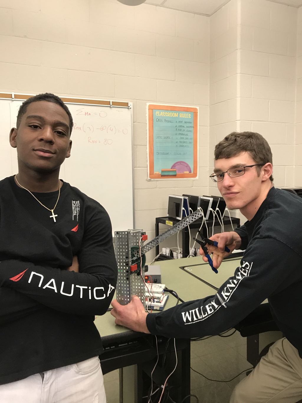
Team Picture:
Paper:
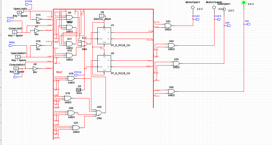
The four inputs that we had were the opening switch, closing switch, open limit switch, and closed limit switch. The outputs were an LED for the gate being open and a LED for the gate being closed. The other two were the motor opening and closing. The gate would start out closed in S0 where Qa and Qb were both 0. Once the open switch was triggered the state became S1 with Qa as 0 and Qb as 1. This was the opening state and the output was the motor going up. Once the arm got to the top the open limit switch was pressed making the state S2 With Qa as a 1 and Qb as a 0. This triggered the open light to be on. then, the closing switch was triggered sending the circuit to the next state (S3) where Qa and Qb are 1 and the arm is closing. Lastly, the arm hit the closing limit switch which made the closed light come on and returned the circuit back to state S0. this whole project was meant to simulate how a toll booth would work in real life.
MultiSim PLD Picture:
VEX Picture:
Conclusion Questions:
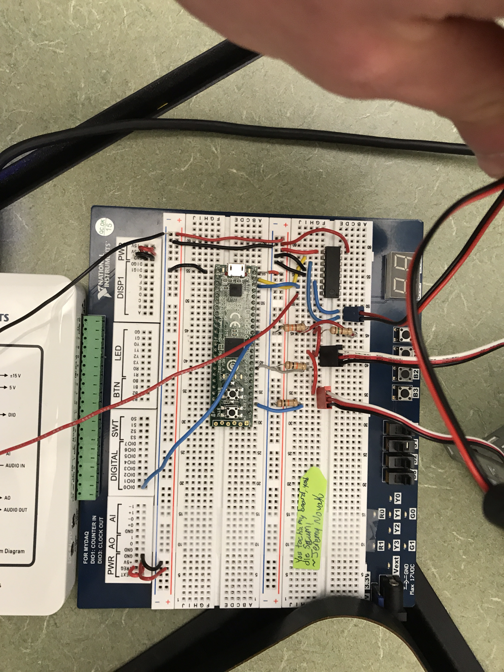
First, Branden and I figured out the states that needed to be created in the state graph. Then, once the state graph was made, all of the inputs and outputs that needed to be set had to be put in place. After that, I the truth table being made so that the logic expressions could be created from it. The outputs for each part of the truth table could be K-Mapped and then the simplified expression could be used to make a circuit that fulfills the necessary outputs. The the circuit was made on MultiSim PLD mode so that it could be uploaded to the "CMOD S6" chip. The bread board needed to be wired so that the circuit would actually work. Pins were assigned to the chip and then attached to the needed outputs. After this the testing began where we uploaded the circuit and saw what happened when the switches were pressed. It took a large amount of time to troubleshoot this project but to summarize the event, we forgot to label our output pins on multisim, and I put the motor controller chip in the breadboard backwards. A nice help in this project was the picture of the breadboard on the PLTW website, this sped up the project immensely, also being able to see pictures of the completed K-maps to check my work was helpful too. There is only one Ms. Zienty and many students, so when I try to get things checked by another, more educated, set of eyes it sometimes takes a long time. With the pictures, this waiting time was alleviated.
